Uni Bremen - MARUM - Sediment Geochemistry - Leobener Str - D-28359 Bremen - Germany
Marine Geochemistry - Laboratory Methods
Converting a sequential sample number into a xy position on a 96-well microplate
Using a CETAC autosampler with 96-well microplates

This page describes equations to convert a sequential sample number into an exact xy position on a series of 96-well microplates. We had to do this, because we wanted to use a standard CETAC (now Teledyne CEATC) autosampler with an instrument software, that sends a rack type and a sample number to the autosampler, but its software does not know microplates as a racktype.

We have done the equations for 96-well type microplates, but with some mathematical skills you should be able adapt them to microplates with 192 or 384 positions. Note that the sample numbers for the equations start with POSition 0  while the microplate positions are numbered 1 to 96.

We use a CETAC ASX 520 autosampler (AS) with both a Varian Vista Pro and an Agilent 720 ICP-OES that are both controlled by XP versions of ICP Expert. Both the Agilent / Varian Software and the CETAC software only know the CETAC rack types and cannot directly deal with microplates. The CETAC ASX software is yet capable of accepting absolute positions in 0.1mm resolution (x and y) and 1mm resolution (z).

We have taught our ASX 520 to access microplates "directly" from the ICP software by doing the following:

We have placed a little computer with 2 serial interfaces between the computer that controls the ICP-OES and the AS. The AS software normally receives rack types and position numbers from the Varian/Agilent software and internally converts them into absolute positions of the AS-needle. What we do is capture those commands with the interface computer and use a software that a skilled colleague wrote for us to convert it to absolute positions on the microplate that we send on to the AS through the second serial port of the computer.

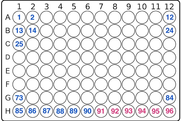
The rack closest to an 8x12 microplate is the rack type 90 (90 sample positions) so when you set rack type 90 in the ICP software you can use it to take samples from 90 of the 96(8x12) positions of the microplate. The graphic representation of the sample positions on the rack in the ICP software will thus be meaningless. The ICP software sample positions are mapped to the microplate like this:


microplate sample numbers


96-well microplate layout. Blue: sample numbers from ICP-software. Red: these samples are not accessable when using a rack type 90. So position 91 will be on the second rack in the ICP software and on the second microplate. Technically it would be no problem accessing the last six positions, we just thought its more intuitive when samples on microplate 1 are only rack1 and position 91 (=position 1 on rack 2) is mapped to the first position on the second microplate.

In the AS software command syntax, all position numbers are one less than the position numbers our ICP software. So in the AS commands the first position is position 0 while in the software and on the racks it is called positon 1

Example:
RACK=90<CR>
POS=23<CR> this is the (23+1)=24th position on the first rack
POS= 120<CR> this is the (120+1) - 1*90 = 31st position on the second rack
POS=<253> is the (253+1) - 2*90 = 74th position on the third rack.

The 10 standard positions are counting separately, so STD=5 goes to the 6th (not sure) of the 10 standard vial positions, but sample positions still start with position 0

When the Varian Software does not want any action from the AS, it sends the command AUX?<CR> about once a second. The AS software answers with OK<CR>. Only because the AS software returns this command, the ICP software knows the AS is online and listening and it shows a little "AS online" sign. It took us some time to find out and include this idle communication in our interface software. If you dont, the ICP software assumes the AS is offline and stops the sequence.

If you want to use the Cetac ASX 520 with microplates, you have to convert the sample positions from a rack that it knows (we use RACK=90 - a 6x15 Rack) into absolute positions.

Microplate dimensions

Microplates have a footprint of 85.5x127.8 mm (approx. 3.4" x 5.0"). In a 96-position (8x12) microplate the hole centers have a distance of  9mm (approx. 0.35") in both x and y directions. The centers of the outer rows have a distance of 11.2mm (approx. 7/16") from the outer edges along the long sides. On the short sides, the centers of the outermost row are 14.3mm (approx. 9/16") away from the outer edges.

The ASX 520 can be controlled to move the needle to absolute positions. The syntax is:
ABS = 2402-300-80<CR>
The three numbers mean: x=240.2mm y = 30.0 mm and z (injection depth) 80mm.
So x and y are given as an integer in 1/10 mm resolution.
x is parallel to the long side of the AS and it counts from left to right
x_max is 4100 (410 mm, 16.1")
y counts from the AS case towards the user. y_max is 2700 (270mm, 10.6")
z counts down in mm  z_max is ?? z=80 means needle tip is 80 mm below home position
The inner dimensions of the plastic guide that holds the standard racks is  18"x10" (457x 254 mm)

Assuming the wellplates stand like the ASX racks with the long side perpendicular to the AS case (long side in y-direction) and using rack type 90 with positions in the software you can convert the sample numbers to x and y positions on the microplate from:

x= x_0+(INT(((POS+6*INT(POS/90)))/12))*90+d_rack*INT(POS/90)

y=y_0+90*((POS+6*INT(POS/90))-12*INT((POS+6*INT(POS/90))/12))

x_0, y_0 are the absolute positions of the first position on the microplate in 1/10 mm (e.g 2.5 mm becomes 25).

d_rack is the offset between one microplate and the next one. More precisely it is the offset between an assumed next row on an endless microplate and the centers of the first row in the second microplate. So it is the distance between the centers of the rightmost row on rack 1 and the leftmost  row on rack 2 minus 9mm (distance between rows)

Position 1 is then in the front left and positions count towards the AS case and rows count to the right.


If the wellplates are positioned with the long side parallel to the AS case the equations change to:


x= x_0+(INT(((POS+6*INT(POS/90)))/8))*90+d_rack*INT(POS/90)

y=y_0+90*((POS+6*INT(POS/90))-8*INT((POS+6*INT(POS/90))/8))

Position 1 is then in row close to the AS case on the left and positions count to the right and rows count towards the user.
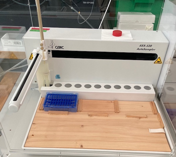
ASX520 w. microplate adapter

We have constructed a quick and dirty adapter that fits smoothly into the plastic guide for the standard racks which can hold three wellplates parallel to the AS case. In the picture, there is a 8x12 pipette tip rack in the first microplate position.

the parameters for this setup are for example:
 
x0 = 140 (=14 mm)
y0 = 440 (= 44mm)
d_rack = 340 (= 34mm)

These numbers can be changed in our little software, that simply contains the equations above as user definable with the only variable being the position POS  (= 0 to 89) that is being sent from the ICP-Software.

In our software the syntax is as follows:

x position:    140+(INT(((x1+6*INT(x1/90)))/8))*90+340*INT(x1/90)
y position:   
440+90*((y1+6*INT(y1/90))-8*INT((y1+6*INT(y1/90))/8))

where both x1 and y1 are equivalent to POS.

If you need to adjust positioning, carefully change the x0 and/or y0 parameters in the equation. We just had to readjust our needle positioning by 2mm to the left by reducing to x0 = 120.

d_rack may be calculated from :
offset_x rack - distance of the left sides of wellplates in x-direction e.g. 142mm
W_x_rack - width of rack in x direction (127.8mm when placed with long side parallel to AS case and  85.5mm when the long sides are perpendicular to the AS case).
d_edge - is the distance of the center of the outermost position on wellplate from the outer edge in x-direction: 14.3 mm when long side of wellplates are parallel to the AS case
and  11.2 when the long side is parallel to AS case
dx - distance of wellplate positions in x or y direction:  dx= 9mm

d-rack = (offset_x_rack - W_x-rack + 2*d_edge - dx) * 10
d_rack = (offset_x_rack -127.8+2*14.3 - 9)*10
d_rack = (offset_x_rack -108)*10
so for offset_x_rack = 142mm we get d_rack = 340 (which is equivalent to an offset of 34mm).

Remark - totally irrelevant for using microplates with Varian/Agilent software, we just happened to find out:

In the Varian/Agilent ICP software you are allowed to mix racks. This only works, because the software pretends to the AS there is only one rack type and renumbers accordingly:
Example: Rack1 is type 90, Rack2 is type 60. if you want to access the 120th sample, it is in the 30th position (POS=29) of the second rack which is type 60. For the AS software you have to code this as RACK=60 POS=89<CR>, because in order to access a position in a type 60 rack in position greater than 1, the positions on rack numbers greater than 1 will be calculated like all previous racks were rack type 60.

Example: to access all 240 samples in three racks: rack 1 = type 90 and rack 2 = type 60, rack3 = type 90 the ICP software uses the command sequence:
RACK=90<CR>
POS=0<CR>  .. POS=1<CR> ..... POS=89<CR>
RACK=60<CR>
POS=60<CR>  POS=61<CR>  ... POS=119<CR>
RACK=90<CR>
POS=180<CR>  POS=181<CR>  ... POS=269<CR>

If this page helped you, you can help us by clicking on our latest research paper in nature geoscience

It is on CO2 release from continental shelves and you can read it for free here

The paper has a wonderful graph that shows the relation between CO2 and sea-level during the last 800,000 years.
It shows impressively how crazy our current CO2 levels are.
.

created 17JUL20
views since 08MAR21
.
page created by M.Kölling