Uni Bremen Home

Marine Geochemistry - Laboratory Methods

Amber Science® 1056 & 3082 conductivity meters
with 529 or 829 flow-through cells

For our Teflon tape Flow injection NH4 analyzer after Hall & Aller we use either an Amber Science 1056 conductivity meter with a 529 flow-through cell or an Amber Science 3082 conductivity meter with a 829 flow-through cell.

Unfortunately, these wonderful little instruments have been discontinued.
As it seems to be hard to find information, we post everything we know about them here:

Amber Science 1056 conductivity meter manual (pdf)
Amber Science 3082 conductivity meter manual (pdf)

Amber Science 529 and 829 flow-through-cell drawing (pdf)
Amber Science  829 flow-through-cell plug wiring (pdf)

Opening the conductivity cell housing

Caution: Do not turn the four large hex screws on the side (5/32" / 4mm Allen). They hold the measuring cell together. If you untighten those, the cell starts leaking and ultimately falls apart! You can fix that, but you will have to take off the case first (which was what you originally wanted to do).

829 cell open  829 cell detail  

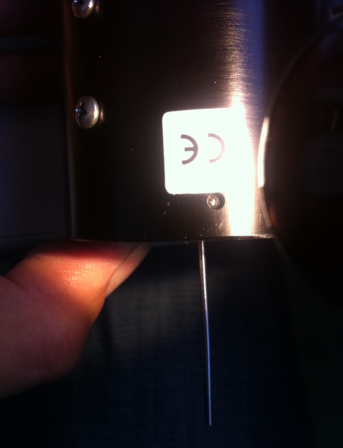
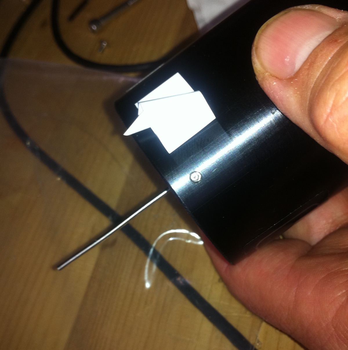
829 cell from outside: Four small Allen screws (1/16" 1.6mm) fix the cell in the cylindrical case. You have to peel off stickers to see them. The Phillips screws are used to fix the whole cell in a box. Take them off (!) before sliding cell out.
Mark the position of the cell in the cylinder case. The screws that fix the 829 conductivity cell in the cylindrical housing are four small (1/16" = 1.6mm) grub screws that can be accessed through holes in the cylinder. These screw holes are covered by stickers that you have to peel off.


829 cell open  829 cell detail  

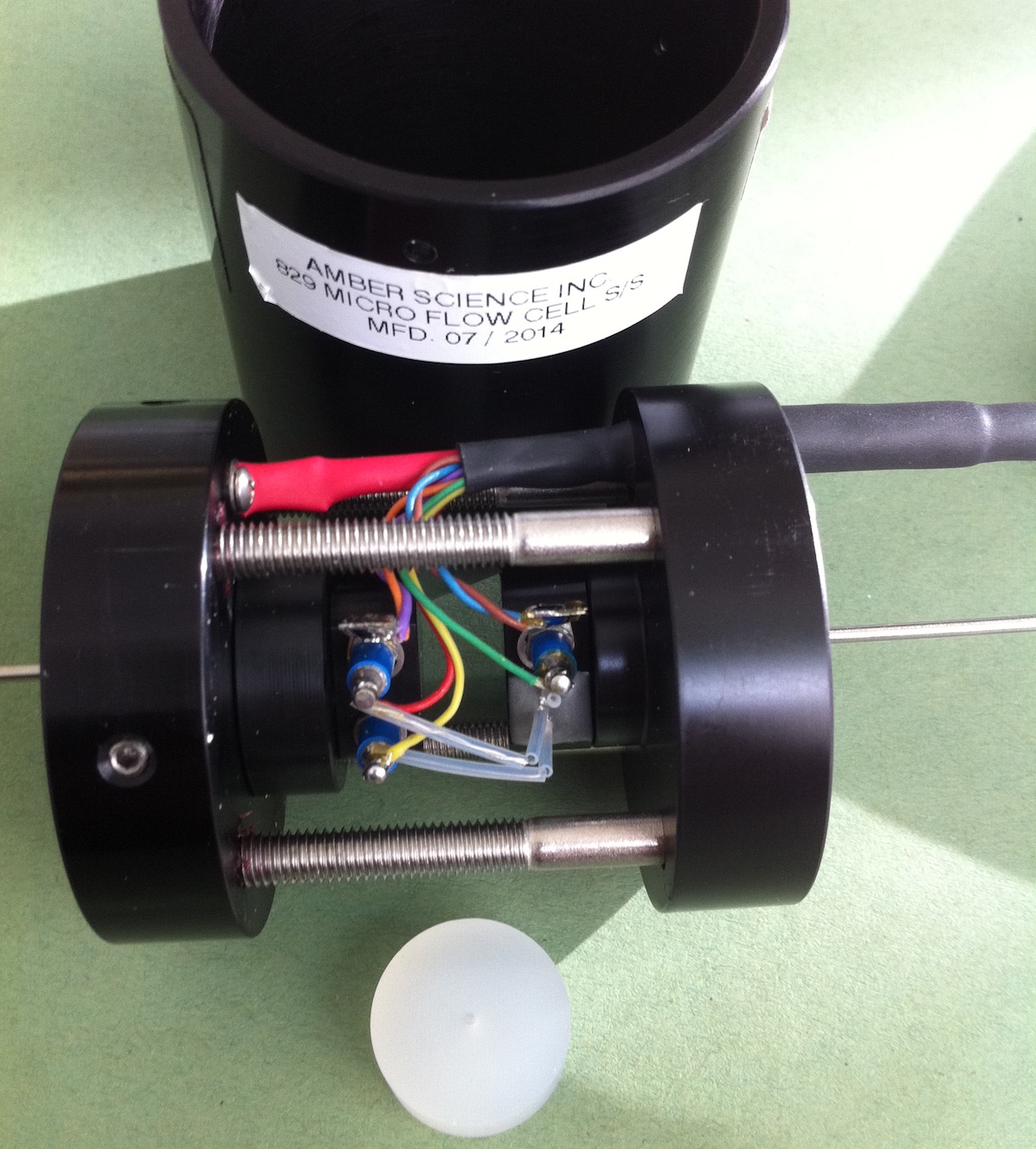
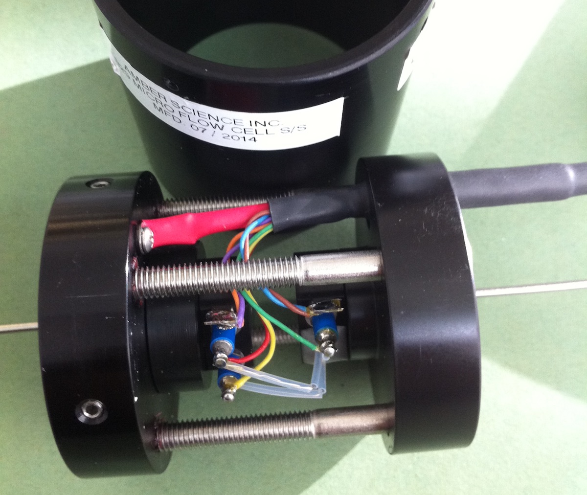
Opened conductivity cell:  Left: 829 cell. You can see the grub screws turned into the aluminum plate (1/16 "= 1.6mm Allen). To separate the cell from the cylinder, turn them clockwise! into the body! Before sliding out the cell, unscrew the Phillips screw(s) (on the outside of the cylinder), if there are any, otherwise it will be hard to slide the cell out of the cylinder.
The white disk is already disassembled
Right: detailed view of the face of the capillary which is glued into a black plastic disc.

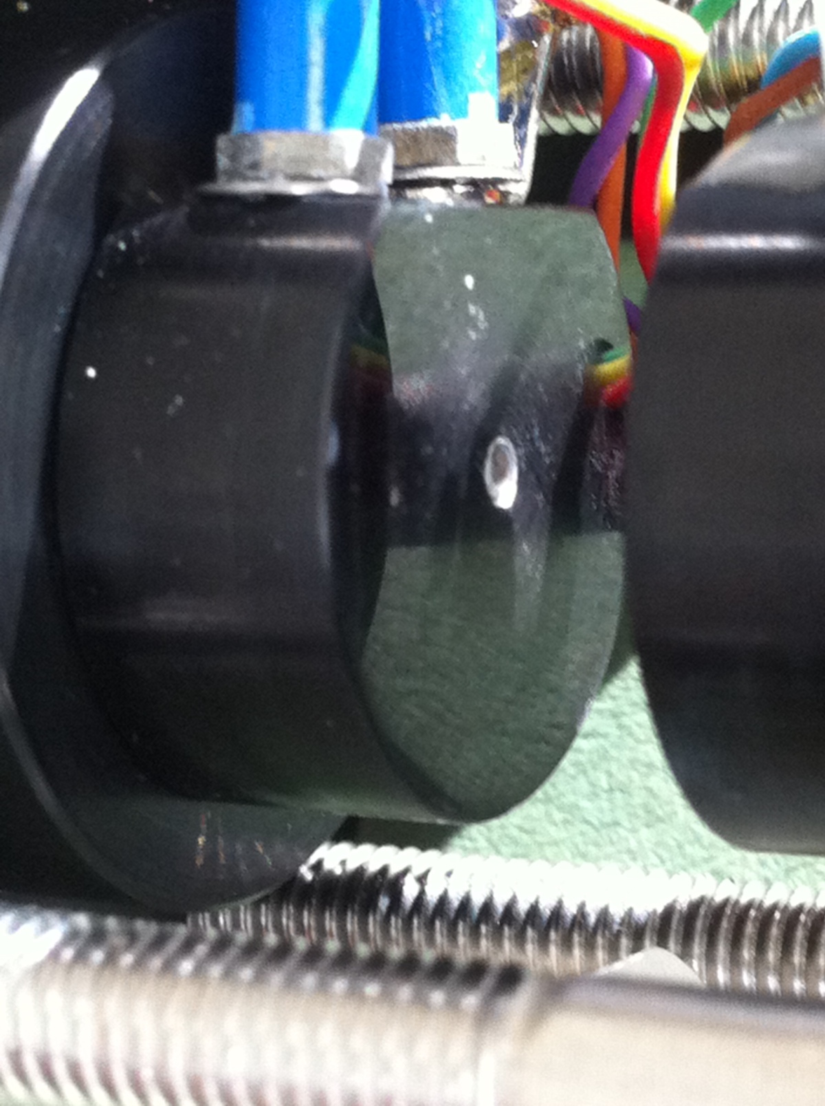
Conductivity cell inside:

The flow-through conductivity cell from Amber Scientific basically consists of two 1/16" stainless steel capillaries, each with one (529 cell) or two ( 829 cell) connecting wires and a temperature sensor that is glued into the capillary holder.
A white plastic (Delrin?) disk is clamped between the two capillaries and represents the measuring cell length.
The plastic disk is 8mm (5/16 ") thick, the bore is 1 mm (0.04"),so the opening has a volume of 6.6 µL. The total length of both capillaries and the bore is 5.5" or 140 mm so the total volume of the amber cell with connection capillaries is about 116 µL.
The connection capillaries are straight standard HPLC capillaries with OD 1/16 "(= 1.6mm), ID 0.04" (= 1mm) and they are 66mm (2.6") long.
The inner sides of the capillaries on both sides of the white disk represent the electrode surfaces. According to the manufacturer the cell constant is 100, i.e. only the last 0.25 mm (1/10") on each side effectively act as electrode surface.
This corresponds to an area of 0.8 mm2 (a factor of 0.008 to the standard area of 100 mm2 with cell constant 1). The cell length of 8 mm corresponds to 0.8 times the nominal distance of the standard cell (10 mm). At 0.25 mm of the inner capillary wall length effectively used as an electrode the cell constant is 0.8 / 0.008 = 100.

The type 529 cell has a 6kOhm @ 25°C NTC as temperature sensor and a 5-pin 180° DIN plug.
The type 829 cell has a double 6kOhm / 30kOhm @ 25 °C NTC as temperature sensor and an 8-pin 270 ° DIN plug (with central pin).
This means that the 829 cell may be connected to an old Amber 1056 measuring device via an adapter (wiring see below - you cannot buy this adapter). The other way (type 529 cell connected to 3082 meter) it doesn't really work, unless you simulate the double wires by connecting the two pins in the 8-pin connector. The second NTC could be soldered directly into the connector - that is not quite the temp on the capillary, but it might work for our purposes. Otherwise you would have to convert the 529 into an 829 which means changing the plug and the cable, connecting it with 2 cables per capillary and replacing the 6kOhm NTC with a 6k/30k double NTC or adding a 30kOhm NTC.
The conductivity wire connections are made using soldered connections that are glued into the Delrin capillary holder with the capillaries. Two soldering tails go to the capillaries, but the pins are only intended as soldering points for the thermistor cables which are not (!) connected to the soldering tails.

829 cell open     529 cell open

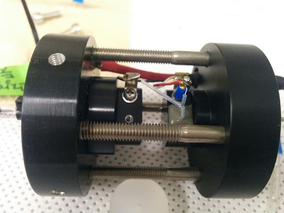
Opened cells:  white plastic disc removed. Left: 829 cell.  Right: 529 cell from 2005 (photo credit Sung-Uk An)


Re-Assembly of the 529 or 829 flow-through conductivity cell

Carefully center the white plastic disc between the capillaries and tighten all four large Allen screws (5/32" 4mm) just enough that the disc remains a bit loose. Since at least three of the screws have Loctite, you have little feeling for how tight the screws actually are!
One after the other - or rather crosswise - tighten all four screws just enough to hold the white disk, and then turn them all back a bit so that the white disk is loose again.
Use a slightly less than 1mm (0.04") wire to align the white disk with the capillaries. A thick (= 0.9mm) nylon wire (fishing line?) or a 0.036" guitar string (that should be the fifth or A string for an electric guitar) or maybe a 1/32" (=0.8mm) PEEK capillary will work fine as well. You might also use the L-shaped cleaning wire that comes with the cell.
Simply stick the wire gently through the capillary, the disk and the second capillary. This only works, if the disk is loose enough. Any bit of misalignment will stop the wire. Then tighten all four screws a little crosswise again (approx. 1/4 turn).

Now everything should be straight and tight. (don't fasten screws too tight - it has to be very straight and aligned, not very tight !!!).
If you just turn the big Allen screws by feeling, it will almost certainly be bending the connection a bit and the cell will be leaking.

Check for leaks: (preferably before refitting the cylinder case!!)
Place the cell on kitchen paper or paper towels so you see it leaking. Fill two disposable syringes half way with water and attach one to each end of the two capillaries with a short tube (should seal well). E.g. the tube end with a female luer-lock connector from a used rhizon works very well).
If all is fine, you should be able to push the water from one syringe into the other and, if necessary, apply pressure to both syringes. if not, it leaks immediately (hence the cell on kitchen paper.).
If it leaks: Unfasten the screws and carefully try to reassemble so the white disk sits perfectly flat and centered between the black pieces.
When everything is "leakproof", insert the cell back into the cylinder and carefully unscrew (= turn them counterclockwise!) the grub screws crosswise (!) (1/16 "Allen key) so that the cell unit is centered the cylinder. The grub screws press against the cylinder from the inside so to fix the cell they have to be turned counterclockwise.

As you see, there is not much that could break in those cells. As long as the capillaries are not blocked and the inner wall of the capillary does not have stains, the cells should work properly. Cleaning may be done with the L-shaped wire provided with the cell or the same wire tha you use for centering the white disk.

Amber Science 3082 Conductivity Meter: Serial port (RS232)

General remark: Only the 3082 model has a digital output. The serial port only delivers exactly what you see on the display. For the setup as a detector in a flow-injection NH4 or CO2 detector it is more precise to use the analogue signal because you have a high background conductivity that prevents the display from showing enough decimals.

Digital recording of data:

Required cable: serial extension (male - female SubD 9-pin)
When you send CR or LF CR to the meter through the serial connection (or automatically if in auto-transmit mode) the device outputs data with the following syntax: (CR = carriage return - hex0D, LF = line feed - hex 0A)

computer: CRLF

Answer from meter:
Data point xxxLF data point number.
Conductivity xx.xx uSLF  5 digits, could also be x.xxx or xxx.x. µS or mS
Temperature xxx.x Deg CLFCR  2 leading spaces

Auto transmit function

When On: Values are automatically transmitted if something changes (at least 2 digits) or if you push the right dial. Settings are transmitted when the left switch is in "self test" and the right dial is pushed. Parameters (cell const etc.) cannot be changed
When Off: Parameters may be changed. Output of data when CR (= hex 0D) is sent from computer program to RS232

 startup output at serial port  software output after CR 

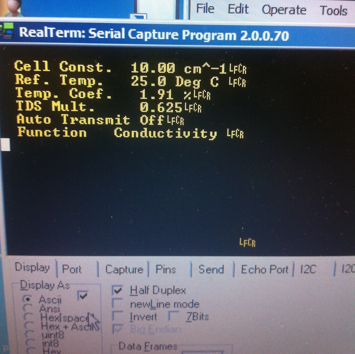
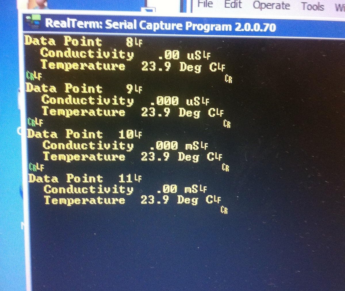
Left: startup output from 3082 serial port. Right: data point output after each CR sent to the serial port

The Amber scientific software for the 3082

There is a DOS / XP software that comes with the device that can write data to files
Very basic, works on DOS and Windows XP
Alt-R:  write to file (new file or append if file exists)
Alt-F:  format .. as a standard 3 lines are output
to output all info in one line (easier to read) press Alt-F 1 (not the function key F1!)
Alt-Q: End file (not quit program like it is standard now)
Esc:   Quit = exit program completely. The file is also closed.
We did not check, but the program should also write directly to a serial printer.

But as mentioned above: Only the digits that can be seen on the display are transmitted digitally. Thus the analogue output is actually much more accurate! The major problem that we have when we use it as a detector in a NH4 flow-injection system is that the background conductivities are high. We use old Knauer strip chart recorders that can compensate for quite a bit (but not all) of zero offset. 

A better way would be to directly compensate for the background conductivity by modifying the setup to become a Wheaton bridge (parallel to measuring cell R1, a second cell R2 with pure eluent). With a fixed resistor R3 and an adjustable resistor R4 you should be able to adjust R1 / R2 = R3 / R4. So if there is pure eluent in both conductivity cells, the current should be 0 if the resistances R3 and R4 are identical

There are precise HPLC conductivity meters that do exactly this - but they are more expensive than the Amber meters were.

Wiring for adapters:

Adapter : 829 cell (270° DIN with central pin) -> 1056 meter (5 pin 180° DIN)

 1 and 6 -> 1 electrode 1
 3 and 7 -> 3 electrode 2
       8 -> 2 ground
       5 -> 5 6k NTC
       2 -> 4 NTC common
       4 not connected (30k NTC)

Adapter : 529 cell - > 3082 meter (8 pin 270° DIN) this is not precise, but might be working

          1 -> 1 electrode 1 cable 1
          1 -> 6 electrode 1 cable 2
          2 -> 8 ground
          3 -> 3 electrode 2 cable 1
          3 -> 7 electrode 2 cable 2
          4 -> 2 NTC ground
          5 -> 5 6k NTC
NTC 30k gnd -> 2
    NTC 30k -> 4

Adapter 829 -> WTW LF 191 (7pin 6x60° DIN w central pin)

      4 -> 1 NTC 30k (829=red)
      5 -> 2 NTC 6K (829=green)
      2 -> 3 NTC common (829=yellow)
      1 -> 4 electrode 1 cable 1 (829=brown)
      6 -> 5 electrode 1 cable 2 (829=blue)
      3 -> 6 electrode 2 cable 1 (829=orange)
      7 -> 7 electrode 2 cable 2 (829=violet)
      8 -> shield (829=blank / Adapter: black)

time stamp 03Feb21

page created by M.Kölling